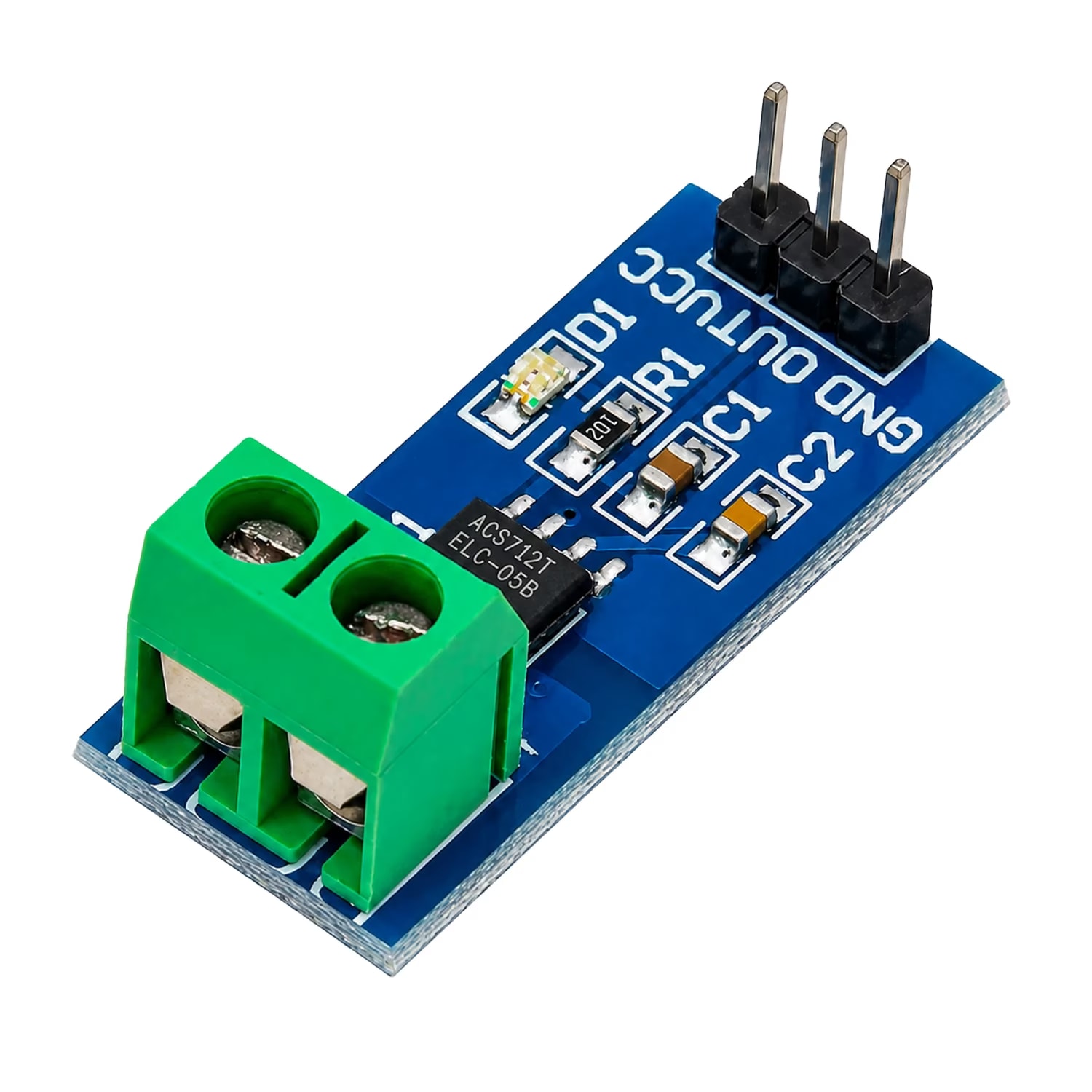
The ACS712 30A Current Sensor Module is a popular electronic module used to measure AC and DC electrical current without directly connecting the measurement circuit to the high-current path. Based on the Allegro ACS712 Hall-effect current sensor, the module converts the magnetic field generated by current flow into an analog voltage signal that can be read by a microcontroller such as Arduino, ESP32, STM32, or Raspberry Pi with an appropriate ADC interface.
The 30A version is designed for measuring currents in the range of approximately -30A to +30A, with a typical sensitivity of 66 mV/A. The sensor operates from a 5V supply and provides a ratiometric analog output.
Because of its simple interface and electrical isolation between the current conductor and signal circuitry, the ACS712 30A module is widely used in DIY electronics, robotics, battery monitoring, motor-control projects, power supplies, and embedded systems.
What Is the ACS712 30A Current Sensor Module?
The ACS712 30A Current Sensor Module is a current measurement board built around the ACS712 Hall-effect current sensor IC.
Unlike a conventional shunt resistor current sensor, the ACS712 detects current by sensing the magnetic field produced by current flowing through its internal copper conduction path.
This provides several useful characteristics:
- AC and DC current measurement
- Bidirectional current sensing
- Analog voltage output
- Electrical isolation between the current path and sensor signal
- Low-resistance current conductor
- Simple interface with microcontrollers
- No external shunt resistor required
The ACS712 family is available in different current ranges, including 5A, 20A, and 30A versions. The ACS712 30A variant provides a nominal ±30A sensing range and 66 mV/A sensitivity.
ACS712 30A Current Sensor Specifications
The following table summarizes the important specifications of the ACS712 30A sensor.
Parameter | ACS712 30A Specification |
|---|---|
Sensor type | Hall-effect current sensor |
Current measurement | AC and DC |
Current range | Approximately -30A to +30A |
Sensitivity | 66 mV/A typical |
Supply voltage | 5V nominal |
Supply operating range | Approximately 4.5V–5.5V |
Output | Analog voltage |
Zero-current output | Approximately VCC/2 |
Typical zero-current voltage at 5V | Approximately 2.5V |
Bandwidth | Up to approximately 80 kHz |
Response time | Approximately 5 µs |
Typical accuracy | ±1.5% under specified conditions |
Operating temperature | -40°C to +85°C |
Current path resistance | Approximately 1.2 mΩ typical |
Current sensing | Bidirectional |
Isolation | Galvanic isolation between current path and signal circuit |
The exact performance depends on the particular ACS712 variant, module implementation, supply voltage, filtering, PCB layout, temperature, and measurement conditions.
ACS712 30A Working Principle
The ACS712 works using the Hall-effect principle.
When electrical current flows through the sensor's internal copper conductor, it produces a magnetic field. The Hall-effect sensing circuit detects this magnetic field and converts it into a voltage.
The output voltage changes proportionally with the current flowing through the sensor.
For the 30A version, the typical sensitivity is:
66 mV/A
The sensor has an output near half of its supply voltage when no current is flowing.
With a 5V supply:
Zero-current output ≈ 2.5V
When current flows in one direction, the output voltage moves above approximately 2.5V.
When current flows in the opposite direction, the output voltage moves below approximately 2.5V.
This makes the ACS712 suitable for bidirectional current measurement.
Basic Output Relationship
For the 30A version, a simplified relationship is:
VOUT ≈ VCC/2 + (Current × 0.066V)
For example, assuming a 5V supply:
At 0A:
VOUT ≈ 2.5V
At +10A:
VOUT ≈ 2.5V + (10 × 0.066)
VOUT ≈ 3.16V
At -10A:
VOUT ≈ 2.5V - (10 × 0.066)
VOUT ≈ 1.84V
The actual output should be calibrated in the real circuit because zero-current offset, temperature, ADC accuracy, noise, and module characteristics can affect the measured value.
ACS712 30A Pinout
Most ACS712 breakout modules expose four commonly used connections:
Pin | Function | Description |
|---|---|---|
VCC | Power | Connect to 5V |
GND | Ground | Connect to circuit ground |
OUT | Analog output | Voltage proportional to measured current |
Current terminals | Current path | Connect the load/current-carrying conductor through the sensor |
The exact labeling and physical arrangement can vary between module manufacturers, so it is important to check the PCB markings or module documentation before wiring it.
The underlying ACS712 IC itself has more pins because the module incorporates the sensor IC into a breakout-board design.
How to Connect ACS712 30A to Arduino
One of the most common applications of the ACS712 30A module is measuring current with an Arduino.
A basic connection is:
ACS712 Module Arduino
-----------------------------
VCC 5V
GND GND
OUT A0
The high-current circuit is connected separately through the sensor's current terminals.
Arduino ACS712 30A Example
A basic Arduino program can read the analog voltage and convert it into an approximate current value.
const int sensorPin = A0;
const float VCC = 5.0;
const float sensitivity = 0.066;
Related products
Components that pair well with this guide.